
DU-BLE
Definition and purpose of the sensor

Definition and purpose of the sensor
The wireless angle sensor with autonomous power supply DU-BLE of the ESCORT trademark (hereinafter referred to as the measuring device, product, angle sensor, DU-BLE) is designed to measure the angular position of deflecting parts of various machines and mechanisms relative to the Earth's gravitational field, determine the direction of rotation (in the corresponding modes) and transmit this data via a radio channel at a frequency of 2.4 GHz.
The measuring device (sensor) "DU-BLE" is used in automotive equipment and other objects where angle measurement is required.
DU-BLE is a completely wireless sensor with autonomous power supply. Sensor data is transmitted in the form of Bluetooth packets in Advertising mode; the frequency of data sending is every 3 seconds.
More detailed technical specifications are presented in the device's data sheet.
Basic Terms and Concepts
Serial Number - a code consisting of a series of letters or numbers assigned to a product (sensor).
Sensor Name - sensor designation among BLE devices, consisting of the first two letters of the sensor model and the last 6 values of the serial number, for example, DU_100100
MAC Address - a unique identifier assigned to each unit of active equipment. It is used to identify devices in the network.
Data Packet - a set of values transmitted by a device equipped with a Bluetooth transmitter, the structure of which is specified by the data transfer protocol.
Data Transfer Protocol - a set of specific rules or agreements of the logical level interface that determines the exchange of data between different programs or devices. In the case of the DU-BLE sensor, the Escort BLE protocol is used to transfer data packets.
Advertising Mode - a data transfer mode in which the device “distributes” data packets at a certain frequency, regardless of the presence of a device receiving the data.
Connection Mode - a data transfer mode in which the transmitter waits for a connection to the receiving device in order to start transmitting data packets.
BLE-RS485 base - a device that retransmits data transmission and converts it from a Bluetooth packet into a data packet transmitted via the RS-485 interface in accordance with the LLS protocol.
BA-BLE base - a device that retransmits data transmission and converts it from a Bluetooth packet into a data packet transmitted via the RS-485 and RS-232 interfaces in LLS and MODBUS protocols.
DU-BLE sensor's design
First generation DU-BLE design

Second generation DU-BLE design

Connecting sensor to a smartphone
To configure the DU-BLE sensor, calibrate it and calibrate the tank, you should use the Escort Configurator application, available on iOS and Android devices (hereinafter referred to as the “application” or "app").
Geolocation
Launch the app and activate Bluetooth and geolocation on your smartphone also check if application have access to geolocation.


Connecting sensor

Press the Sensor Settings button. Next, select DU-BLE.


Find the required sensor by typing the last 6 digits of its serial number. You can find the serial number on the sensor head.
You can also simply select the required sensor from the list and click the Connect button. On an Android device, you can click on the sensors name, and a package of data received in advertising mode will be displayed.


Setting a password
It is strongly recommend that you set a password on the sensor in order to restrict access to its settings. When you connect for the first time, the application will ask you to set a password automatically.
You can set, change and delete a password in the Additional Features.

Then, in the field that appears named "Password for changing settings", enter the password that you want be used later and click Enter.

PLEASE NOTE THAT THE PASSWORD RESET PROCEDURE CAN BE VERY TIME-CONSUMING. WE RECOMMEND THAT YOU TAKE A RESPONSIBLE APPROACH IN SETTING YOUR PASSWORD AND SAVING IT.
Also note that the password cannot start with 0.
To delete a previously set password, you must enter it in the Password field, and then press the Enter and then the Delete buttons.
Attention! By default, there is no password set on the sensor! If you connected the sensor and a password was already set on it, contact technical support.
Main sensor parameters
To see the main parameters of the sensor go to the Data tab. There you can see the following parameters:
- RSSI - Received signal strength indicator, which indicates how well your smartphone receives sent data. This parameter is not transmitted by the sensor, but is calculated by the receiving device
- Vbat or sensor battery charge (3.5V or higher indicates the battery is fully charged; 3.2V or lower indicates the battery is low and should be replaced)
- Sensor serial number
- Firmware version (FW) installed in the sensor
- Current Operating mode set on the sensor
- The sensor's MAC address is used to connect the sensor to compatible external devices
- Current sensors readings in selected working mode
- Button for setting 0 as current angle of the sensor

The battery voltage drops to 3.2V for 10-15 seconds - this is normal (especially if this happens after rebooting the sensor by removing the sensor battery and then installing the battery back). This is due to the fact that all processes in the sensor (measuring level, temperature and battery voltage, as well as sending a data packet) are launched simultaneously, thus energy consumption increases, which leads to a temporary decrease in battery voltage.
Operating mode
Для установки режима работы на датчике, перейдите в меню настройки.

| Name of the mode | Description of the mode | Format of transmitted data |
| Transportation | Used for transporting and storing the sensor. The accelerometer is turned off to save power; no measurements are taken. | |
| Vertical rotation control | It is used to determine the direction of rotation of the sensor in a plane parallel to the plane of the sensor installation (except for rotation parallel to the ground plane) and/or counting revolutions and speed (rpm).
Horizontal rotation - the sensor is installed along the axis of rotation of the concrete mixer with the convex part of the body at 90° relative to the ground. Vertical rotation - the sensor is installed perpendicular to the axis of rotation of the concrete mixer. |
1. Direction only 0 - no rotation 1 - left rotation 2 - right rotation (you can set these values yourself) 2. Number of revolutions, rotation speed (rpm), direction of rotation is shown as + or - |
| Horizontal rotation control | ||
| Container | It is used to control the loading of equipment, for example, a garbage truck | The tilt angle and the container cumulative counter are transmitted |
| Bucket | Serves to determine the operation or downtime of an excavator and similar equipment | The tilt angle and operation are transmitted depending on whether the equipment is working or idle |
| Plow | Serves to determine the operation of the snowplow blade of snow removal machines and similar equipment | The tilt angle and operation are transmitted depending on whether the equipment is working or idle |
| Angle control | Serves to determine the angle of inclination of parts of mechanisms relative to the horizon. Triggering events occur when a certain angle set by the user is reached. | The tilt angle and response are transmitted depending on whether the control element of the equipment is lowered or raised, respectively |
| Horizontal inclinometer | In the “Single-axis” measurement mode, the sensor records deviations only along one axis - the pitch axis - from the zero point, which must be set after selecting the mode and installing the sensor at the moment when the mechanism is on a flat surface in the stowed position. The angle is measured from 0 to 360 degrees.
In the “Two-axis” mode, you can track the tilt angle along each measurement axis separately. |
The roll (and pitch) angle(s) is transmitted.
0-360 for one axis 0-180 for the other axis |
| Verticalinclinometer | In the “Single-axis” measurement mode, the sensor records deviations only along one axis - the pitch axis - from the zero point, which must be set after selecting the mode and installing the sensor at the moment when the mechanism is on a flat surface in the stowed position. The angle is measured from 0 to 360 degrees.
In the “Two-axis” mode, you can track the tilt angle along each measurement axis separately. |
The roll (and pitch) angle(s) is transmitted.
0-360 for one axis 0-180 for the other axis |
Vertical rotation control


- Selecting the format of transmitted data (Direction only or Speed and rpm)
- Selecting the transmitted values of rotation left and right, available only in the "direction only" transmission format
The sensor is installed at the ends of the mixer.
This mode has 2 formats of transmitted data:
1) Direction only - used, for example, to control the direction of rotation of a concrete mixer. Depending on the direction of rotation around the axis, a trigger event is transmitted: when rotating to the right, the value 1 will be transmitted, when rotating to the left - the value 2, if there is no rotation, 0 will be transmitted.
You can change the value of rotation to the left and to the right (from 1 ... 255)
2) Speed and rpm. The sensor will transmit the number of complete revolutions and the rotation speed in rpm. The rotation speed will be calculated by the sensor after the first three full revolutions. The speed will be positive in one direction, negative in the other. You can learn more about how to set up speed recognition on the monitoring platform in this manual


Horizontal rotation control

- Selecting the format of transmitted data (Direction only or Speed and rpm)
- Selecting the transmitted values of rotation left and right, available only in the "direction only" transmission format
The sensor is installed at the ends of the mixer.
This mode has 2 formats of transmitted data:
1) Direction only - used, for example, to control the direction of rotation of a concrete mixer. Depending on the direction of rotation around the axis, a trigger event is transmitted: when rotating to the right, the value 1 will be transmitted, when rotating to the left - the value 2, if there is no rotation, 0 will be transmitted.
You can change the value of rotation to the left and to the right (from 1 ... 255)
2) Speed and rpm. The sensor will transmit the number of complete revolutions and the rotation speed in rpm. The rotation speed will be calculated by the sensor after the first three full revolutions. The speed will be positive in one direction, negative in the other. You can learn more about how to set up speed recognition on the monitoring platform in this manual
The sensor is installed on the side surface of the mixer.
In horizontal rotation, the sensor is installed with the convex/semi-circular part up or down! When installed with the convex/semi-circular part to the left or right, rotations will not be counted!


Container


Serves to control unloading and loading on equipment types such as garbage trucks, dump trucks, etc., as well as for more precise control of hatch cover opening.
After installing the sensor, zero should be set. The equipment should be located on a level surface. When crossing the lower and upper threshold values, the number of trips will increase and the total activation counter will be transmitted.

When crossing the blue line (Upper threshold value), the counter increases by 1, for repeated triggering it is necessary to cross the green line (Lower threshold value)
Black line - Zero
Green line - Lower threshold value
Blue line - Upper threshold value
The counter will continue to increase with each container up to the maximum value of 65535. After which it will reset to zero and continue to increase again. With 100 containers per day, the counter will last for 1-2 years.
The settings for the received readings on the platform are shown in this manual
Bucket


This mode is intended for use on excavators to monitor bucket operation or idle time.
Filtration level - how much the tilt angle data will be filtered during sudden changes.
Delta - the minimum angle value at which the triggering occurs.
Measurement interval - the time period after which the tilt angle is compared to calculate the delta.
Turn OFF delay - the time period during which the work will be transmitted.
Transmit as event notification- the value that will be transmitted as work.
"Measurement interval" sets the time during which the sensor measures the angle values. After the measurement interval, the current value is compared with the previous value. If the difference is a certain angle that is greater than or equal to the "Delta" value, then the triggering will occur, which will signal the excavator bucket is working. The "Delta" parameter sets the minimum angle value at which the triggering occurs. If the bucket operation is stopped, the angle difference will not exceed the set value "Delta", the "Turn OFF delay" is started, no triggering occurs (the value "0" is transmitted). In this way, the bucket operation and downtime are separated, eliminating false triggering.
The setup of the received readings on the platform is shown in this manual
When installing tilt angle sensors on excavator manipulators, it is recommended to place the sensor on the knee of the manipulator, which is the most active at the time the excavator is performing work and makes a greater number of movements with a greater amplitude of angle change.


Plow


The mode is designed for installation on "blade" type devices, such as snow blowers used for clearing roads, or a bulldozer.
Filtration level - how much the tilt angle data will be filtered during sudden changes.
Upper limit - the tilt angle threshold above which the alarm stops.
Lower limit - the tilt angle threshold below which the alarm starts after the turn-on delay.
Turn ON delay - the number of seconds the sensor must be below the lower threshold to start the alarm.
Turn OFF delay - the number of seconds the sensor must be between the upper and lower angles to stop the alarm.
Transmit as event notification - the value that will be transmitted as the job.
Important! It is not recommended to use the sensor to control mechanisms whose deviation amplitude is less than 10 degrees. For example, the middle blade of a grader.
When crossing the "LOW" boundary towards a smaller angle, the turn-on delay timer is started. If the current angle does not exceed the "LOW" boundary upon expiration of the turn-on delay timer, the triggering event will occur (the value "1" or another value that you set is transmitted).
When crossing the "LOW" boundary towards a larger angle, the turn-off delay timer is started. If the current angle remains greater than the "LOW" boundary upon expiration of the turn-off delay timer, the triggering will be reset (the value "0" is transmitted).
If, at the moment of counting down the turn-off delay timer, the sensor crosses the "LOW" boundary back towards a smaller angle, the started turn-off timer is reset.
When crossing the "UP" boundary towards a larger angle, the triggering will be reset instantly.
This is done to obtain more visual readings of the sensor triggering (short-term raising and lowering of the implement during obstacle avoidance and turns are excluded).
The "0" is set in the working position.


The setup of the received readings on the platform is shown in this manual
Angle Control


The "Angle Control" operating mode can be used, for example, to control the operation of a garbage truck, dump truck, and other working units of special equipment.
The 3-axes accelerometer used in the sensor cannot ignore vibrations, acceleration and deceleration of the vehicle/unit the sensor is installed on. It also cannot ignore the inclination of the terrain the vehicle/unit moves across.
Due to that the sensor is less suited for the monitoring of machinery units that are operated when on the move, f.e. dump trucks that are gradually unloaded with their boxes are lifted and they slowly move forward. There will be factors mentioned above that will affect the sensor's readings and cause random angle changes that will be impossible to reliably validate by the vehicle's speed.
In other cases the sensor's readings can be validated by the vehicle's speed.
More on that in this manual (p. 19)
The sensor also has its own filtration/smoothing algorithm. However, the higher the level of that filtration is, the slower the current angle reading is calculated and that could lead to the actual movements of the mechanism the sensor is installed on to get missed.
One more option is to install 2 sensors: one on the vehicle's (unit's frame) and another - on the mechanism that needs to be monitored. More on that in this manual (p. 17)
Filtration level - how much the tilt angle data will be filtered during sudden changes.
Upper limit- the tilt angle threshold above which the triggering occurs.
Lower limit- the tilt angle threshold below which the triggering stops.
Transmit as event notification - the value that will be transmitted as work.
When the angle increases and the upper limit is reached, the sensor is triggered; when moving backwards and crossing the lower limit, the triggering is reset (the value "0" is transmitted).

The setup of the received readings on the platform is shown in this manual
Horizontal inclinometer


The inclinometer mode is designed to measure the angle and direction of tilt.
Filtration level - how much the tilt angle data will be filtered during sudden changes.
Single-axis mode: measures the rotation angle along the X axis (roll) in the horizontal position, i.e. the ZY plane is perpendicular to the installation plane. It is possible to set zero. The measurement range is 360°. There is no trigger event.
Dual-axis mode: measures the rotation angle along the Y axis (roll) and the rotation angle along the X axis (pitch) in the horizontal position. It is possible to set zero. The measurement range is 180°. There is no trigger event.
Data transfer in Horizontal inclinometer mode is supported only when using BA-BLE

Vertical inclinometer

The inclinometer mode is designed to measure the angle and direction of tilt.
Filtration level - how much the tilt angle data will be filtered during sudden changes.
Single-axis mode: measures the rotation angle along the X axis (roll) in the horizontal position, i.e. the ZY plane is perpendicular to the installation plane. It is possible to set zero. The measurement range is 360°. There is no trigger event.
Dual-axis mode: measures the rotation angle along the Y axis (roll) and the rotation angle along the X axis (pitch) in the horizontal position. It is possible to set zero. The measurement range is 180°. There is no trigger event.
Data transfer in Vertical inclinometer mode is supported only when using BA-BLE

Sealing and installation
Connection dimensions
Connection dimensions of the DU-BLE of the former design


Connection dimensions of the DU-BLE of the current design


Sensor sealing
Sealing DU-BLE of the former design
To seal the sensor and prevent unauthorized access to it, install the protective cover and pass the seal through the special holes in the cover. Tighten the seal against its end into the special hole in the seal. Cut off the excess wire of the seal.

Sealing DU-BLE of the current design
You will need the sensor protective cover and the seal provided in the kit
-
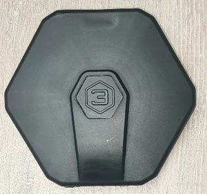
Protective cover DU-BLE
-
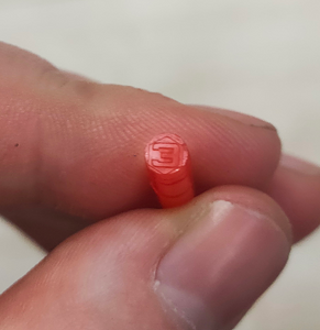
DU-BLE seal


The cover is attached to the sensor head

Then the seal itself is fixed in a special hole (it must be inserted to the end, with the closed end facing outward)
-
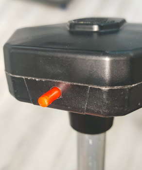
Installing DU-BLE seal
-
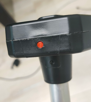
Installed DU-BLE seal


To remove the seal, screw in the special key from the kit (you can also use any self-tapping screw of suitable size) and pull it towards yourself.


This makes it impossible to remove the seal without damaging it. This provides additional protection against unauthorized access.
Alternative sealing for DU-BLE of the current design
Also included with the current DU-BLE is an alternative seal if a numbered seal is required.
- The wire must be threaded through the hole in the sensor cover

- Thread both ends of the cable through the hole in the sensor head

- Pass both ends through the seal, tighten the cable and install the seal by pressing the protruding part of the seal

Mounting and direction
The most common mounting method is self-tapping screws with a sealing washer. It is also possible to install on threaded crimp nuts, welded bushings and other structural elements. The sensor can be mounted on pre-prepared places using screws and bolts with strength class not less than 4.8. It is necessary to ensure tightness of the connection between the sensor body and the tank. For additional protection it is allowed to use automotive oil and gasoline resistant sealant.
For plastic tanks rivets and bolts can be used.

How hard to screw in self-tapping screws

Firmware update (FW)

To update the firmware on the DU-BLE:
- Download the current firmware version as a file to the phone memory
- Connect to the sensor
- Go to “Additional Features”
- Go to FW update

- Select the firmware file (1) from the phone memory (The firmware file is the .zip archive itself, no need to unzip it) and start the flashing process (2). These actions should be performed within 30 seconds after entering update mode!

- The flashing process should start. Do not close or minimize the application during the flashing process!

- When the updating is completed, a window will pop up indicating that the update was successful

Firmware update via the IOS mobile application is shown in this video
Up-to-date firmware can be found in the Download materials
The firmware file is the .zip archive itself, no need to unzip.