
Teltonika-BLE: Difference between revisions
No edit summary |
|||
| Line 1: | Line 1: | ||
[[es:TD-BLE]] | [[es:TD-BLE]] | ||
= <big>''' | = <big>'''Quick start: Connecting Escort BLE sensors to Teltonika trackers via Bluetooth'''</big> = | ||
= Direct BT connection (no adapter) = | = Direct BT connection (no adapter) = | ||
Revision as of 17:10, 16 January 2026
Quick start: Connecting Escort BLE sensors to Teltonika trackers via Bluetooth
Direct BT connection (no adapter)
Currently, the TD-BLE, DU-BLE and TL-BLE are compatible with certain Teltonika models (see the list on the last page of this document; note that it is not definitive; for a more precise list, please, contact Teltonika’s tech support).
- Up to 4 sensors can be connected to the majority of different Teltonika models via Bluetooth
- In case your tracker has the Rs485 port, the sensors can be connected to such tracker by means of the BLE-Rs485 adapter (also called ‘base’ sometimes)
1.Before connecting the sensor, find its MAC address via Escort app for Android devices (Apple devices don’t give access to MAC addresses of any devices) or directly on the sensor’s body (Fig.1 and Fig.2).

|

|
| Fig.1 MAC address in the app | Fig.2 MAC address on the sensor’s head |
2. In the Teltonika configurator, go to the Bluetooth tab first. Make sure that everything is configured as shown on the Fig. 3 below

3. On the Bluetooth 4.0 tab (Fig. 4), configure the BLE Scan settings as follows:
- disable the Non Stop Scan
- set update frequency at 30 seconds (this is the min value)
- BLE scan duration should be 15-20 seconds
- Scan retries until error can be left at 30 (this is actually how many times the tracker will try to get any data from the sensor before sending a connection error code in case of a loss of connection with the sensor)
- Set BT Power level to 7
- switch the BLE Connection control to Allow
4. Further below you have 4 Connection slots to connect up to 4 sensors (those can be any TD, DU or TL sensors). Click on the Advanced button and then enter the MAC address of the sensor (Fig. 4).

5.Then, click on the preset button (Fig. 5) and select the preset required for a certain sensor model and click on the Load button (Fig. 6):
- “escort fuel” for TD-BLE,
- “escort luminosity” or “escort temperature” for TL-BLE, “Escort_DU-BLE_Angle_sensor” for DU-BLE


I/O tab settings
6. Next, go to the I/O tab (Fig. 7) and select the Low option in the Priority column for the BLE Fuel Level and BLE Temperature (BLE Battery Charge is optional) parameters for TD or TL-BLE sensors (luminosity = fuel level).
In case of a DU-BLE, you may want to set the Operand option to the On Change and configure the Event Only option as Yes for the BLE Temperature parameter that corresponds to the Event notification sent by the sensor. Then, whenever the sensor’s Event Notification changes (it might be happening every time the tap of a hatch is opened, for example), the tracker will transmit an extra message to the server immediately upon receiving a new Event Notification.

Fig. 7 I/O tab
To find the io_ you need on the monitoring platform, check the following table:

System settings
7.In the System tab, click on the Codec 8 Extended option (Fig. 8)

Fig. 8 System. Data Protocol. Codec 8 Extended
8. When selecting the installation spot for the tracker, check the RSSI (Signal Strength) in the Bluetooth 4.0 tab by clicking on the Discover BLE button during 2-3 minutes (Fig. 9).
The average value must be from -45 to -85 dB for optimal connection stability.
 Fig. 9 Checking RSSI is vital
9. Remember to orient the sensor with the tracker so that the sensor’s and the tracker’s Bluetooth antenna were facing each other (Fig. 10)

Fig. 10 Sensor and tracker orientation (applicable to both TD-BLE and DU-BLE models)
10. The “io_” parameters (Fig. 11) you need to find in the tracker’s messages on the platform are as follows:
Fig. 11 Connections and IO list
11. Remember to click on the Save to device button after changing any configurations in the Teltonika configurator to apply the changes.

Fig. 12 Saving the changes
Connecting BLE via adapter (BLE-Rs485 base)
1. First, connect the adapter to your C200M or other Rs485-USB converter and connect the USB cable of the converter to your laptop or computer. It is better if all 4 wires of the adapter are connected to the converter: orange to orange (Rs485 Line A), white to white (Rs485 Line B), black to black (GND) and red to red (PWR) (Fig. 13).

Fig. 13 Connecting the adapter to the C200M and to the PC
2. In the Escort configurator for PC, select the COM port that corresponds to the converter that you are using to connect the adapter (to find its number, check the Windows Device manager’s COM and LPT ports section; C200M will be defined there as STMicroelectronics Virtual COM port device). Then go to the BLE then click BLE adapter settings (Fig. 14)


Fig. 14 Connecting the adapter in the configurator (the screenshots are taken from 2 different computers this is why the COM number doesn’t coincide)
3. You will see 4 different cells to connect up to 4 sensors (if the base has the FW 2.3.8 and the configurator is of the 1.0.2.38 version, you need to scroll down to see more cells) (Fig. 14 and 15)

|

|
| Fig. 14 FW 2.3.5 or older of the base
and the configurator 1.0.2.37 or older |
Fig. 15 FW 2.3.8 or newer of the base
and the configurator 1.0.2.38 or newer |
4. Connect the sensor to the first cell before anything else. Click Connect sensor (Fig. 16) and then enter the first letters of the sensor’s model (TD, DU, TL or TH), the lower dash _ will appear automatically. Then enter the 6-digit serial number of the sensor, its password and then click Establish connection (Fig. 17)

|

|
| Fig. 16 Click Connect sensor or Connect another | Fig. 17 Enter sensor´s letters with serial number
and the password and click Establish connection |
5. For each sensor the base can use 1 or 2 network addresses to transmit the 2 main parameters via the main one and the 2 additional parameter via the auxiliary address. The additional parameters can be switched off (Fig. 18)
TD-BLE: level and temperature via the main address, the battery charge (3.5-3.7V) and the RSSI value via the auxiliary address
TL-BLE: luminosity and temperature via the main address, the battery charge (3.5-3.7V) and the RSSI value via the auxiliary address
DU-BLE: angle value and battery charge (3.5-3.7V) via the main address, the event notification and the RSSI value via the auxiliary address (if the FW of the base is 2.3.8 or newer; in the base with the FW 2.3.3 or older the event notification and the battery charge are switched)
 Fig. 18 Switching the additional parameters off
6. Once the sensor or several sensors are connected to the base, make sure to configure the Rs485 tab of the Teltonika configurator so that the tracker were able to send requests to the network addresses that the base uses to “channel” the data that comes from the sensors (Fig. 19)

Fig. 19 Configuring network addresses
7. Then disconnect the base from the C200M or other converter, connect it to the power supply (black and red wires, the fuse from the kit must be installed in the red wire between the adapter and the power supply) and the orange to the line A Rs485 of the tracker and white to the line B Rs485 (Fig. 20)
 Fig. 20 Wiring of the base and the tracker via the Rs485 port
8. In the I/O tab of the Teltonika configurator, select the priority Low (Fig. 21). For DU-BLE’s event notification consider setting Event Only to Yes and the Operand to On Change.
The DU-BLE’s event notification can be transmitted either as a LLS Fuel Level parameter (if the adapter/base has the FW 2.3.8 or newer) or as a LLS Temperature parameter (FW 2.3.3 or older).

Fig. 21 I/O tab LLS parameters
9. The io list for the wired adapter (as well as for the wired sensors) is partially shown below


Fig. 22 io_ list (partial)
10. When selecting the spot to install the adapter on, be sure to assess its average RSSI value over the course of 2-3 minutes in the Escort configurator (Fig. 23). It must be falling into the range from -45 to -85 dB
 Fig. 23 RSSI check
11. Properly orient the Bluetooth antennas of the sensor and the adapter (Fig. 24)


Fig. 24 Orienting the adapter and the sensor
Connecting TH-BLE via Rs485-BLE adapter/base
The TH-BLE sensor can be connected to any Teltonika only via the BLE-Rs485 adapter (as of 1st of July, 2021).
The sensor transmits several parameters. Their list varies from one (earlier release) version to the other (newer release) version.
They are: atmospheric pressure (earlier release only), temperature, humidity, luminosity (newer release only), battery charge.
The RSSI parameter is calculated by the BLE-Rs485 adapter. It is not transmitted by the sensor.
In case of a TH-BLE, the adapter/base can use up to 2 addresses to channel the data that comes from the sensor.
Depending on the preset you select, the order in which the parameters are transmitted to the tracker changes (Fig. 25 and 26).


Fig. 25 Selecting preset Fig. 26 Parameters transmitted via addresses 1 and 2
BLE Fuel Level missing in I/O
If you cannot find the BLE Fuel Level parameter in the I/O tab of a newer version of Teltonika configurator, please, use one of the old ones available via the links below.
The links allow you to download a compressed file with an old FW version (you don’t need to install it onto the tracker) and an older version of the configurator for different tracker models.
The password for the compressed file is 1234
Lost Connection
If there is a connection loss, after several attempts to collect the data (the Scan retries until error setting in the Bluetooth 4.0 tab) the tracker will transmit the error code 3000/300 in the temperature io. The level value will be transmitted as the last reading transmitted by the sensor if it was connected via the BLE base, or 0\-4\65532 in the fuel data.
Before installing a BLE sensor and a tracker, you need to check the stability of the Bluetooth connection to select the best spot to install the GPS tracker/gateway (or BLE-RS485-RS232 adapter) at to minimize the risks of connection losses happening in the future.
To determine if the connection between the Bluetooth transmitter of the sensor and the Bluetooth receiver is stable or not, you should use the RSSI parameter. When you search for a place to install the GPS tracker, you should calculate the average RSSI (Received Signal Strength Indicator) by taking into account the 10 or more measurements of the RSSI taken over the course of 2-3 minutes while the engine of the vehicle is running and all electronics inside the cab and around the vehicle are switched on.
The reason why the RSSI should be taken as the average value is that the RSSI itself is a dynamic parameter, its value changes constantly. This average value must be within the connection stability range.
In case of the Bluetooth 4.0 the connection stability range is the value from -35 dBm to -85 dBm. If the average RSSI is less than -85 dBm (for example, -90 dBm), placing the tracker/gateway where it was during the RSSI check will most probably lead to the connection instability. As a result, not all the sensor's data packages will be received by the tracker.
The solution is to try and turn the tracker around a bit or move it closer to the sensor and placing it at a spot where the average RSSI will be within the -35...-85 dBm range. Alternatively, you could install our BLE-RS485-RS232 BA_BLE adapter/base that tends to perform better than the Bluetooth modules of the trackers.
Please, note that the RSSI is calculated by the receiver, so the connection quality is determined by the receiver and also depends on the receiver's sensitivity.
Presets
You can also downolad our TD 150 BLE and DU BLE presets for Teltonika tracker manually
- First of all, download preset file from the links below: TD 150 BLE DU BLE
- .Follow the Teltonika settings in the right corner below in the configurator
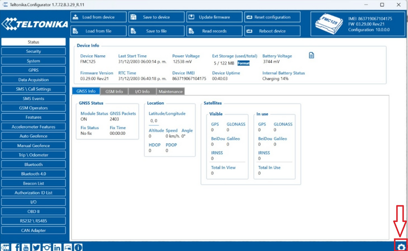
- Open Preset Settings and find preset file, that you downloaded earlier
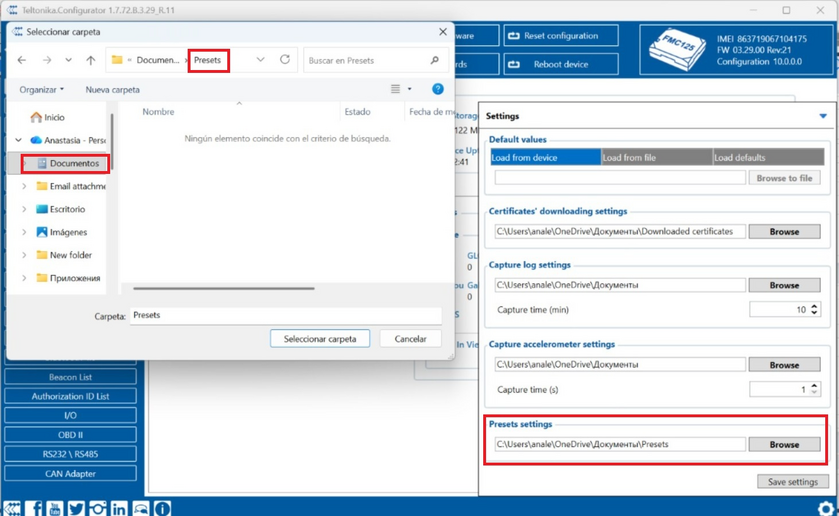
- Choose the downloaded preset file
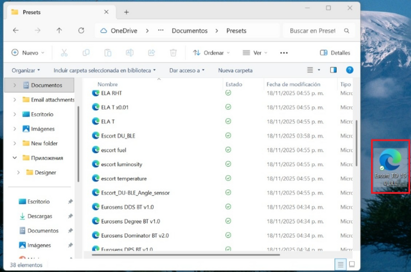
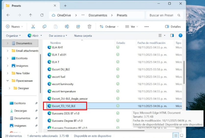
- After that you will find our preset file in the preset list


Compatibility list
FMB110, FMB120, FMB122, FMB125, FMB130, FMB900, FMB920, FMB001, FMB010, FMB202, FMB204, FMB962, FMB964, FM3001
FW: 03.25.15.Rev.01
Configurator: 1.5.5_B.3.25_C.100
Link:https://drive.google.com/open?id=1_QeVFGrHnaVOtXIrmK2oZH7CouotzCYV
FMU125, FMU130, FMM125, FMM130, FMC125, FMC130
FW: 03.25.15.Rev.87
Configurator: 1.5.6_E.3.25_C.083
Link:https://drive.google.com/open?id=1GP-rGLIcjRqO4afI7aufZx_arwy32z8Y
FMB140
FW: 03.25.15.Rev.143
Configurator: 1.5.5_E.3.25_C.142
Link:https://drive.google.com/open?id=1ANb4mzA6RIqGTvAuEM97NiPc2FnNVqDS